Data and Data Panel
In order to simulate you will need data. In order to input, modify and visualize the data of your vase, click on the following button:  . The button is located on the ribbon where data manipulation makes sense. By clicking on the button, you will oppen the data manipulation windows.
Different usage are possible with this Data Panel:
. The button is located on the ribbon where data manipulation makes sense. By clicking on the button, you will oppen the data manipulation windows.
Different usage are possible with this Data Panel:
- Modelization of a new analysis case.
- Visualization of Excel imported data to validate them trough visual and synthetic views
- Interaction with the data though the interface to adapt different scenarios, make different simulations with slightly different datasets or change input data
The creation and edition process of data is similar in all the different tabs of the data manipulation window:
- Adding a new data can be done by right-clicking on the tables or by clicking on “new” in the menu
- Editing the data is achieved by double clicking on the cell to modify
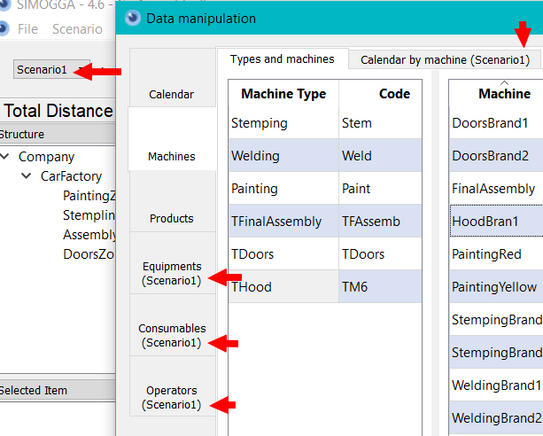
Data are either global or scenario specific Data that are specific to a certain scenario are indicated in the title bar. The scenario that is being parametrized is always the present scenario.
Calendar
The first tab of the data manipulation panel concerns the calendar and time parameters. Here will be defined everything that is related to time management: time period, shifts, time availability, operators availability, machines opening hours(etc.)
Global
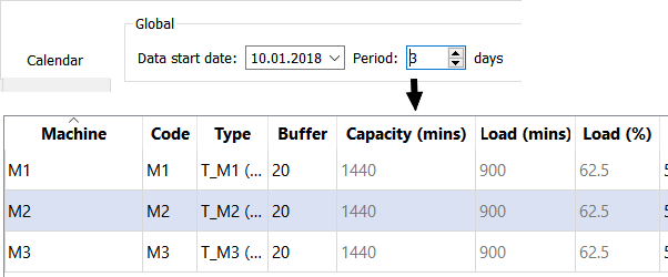
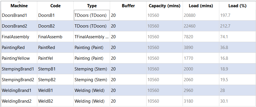
Before input of the parameters into the calendar, a span date and time period have to be defined. In the following example, the extraction data of the data is the 10th January 2018 and has a time period of 3 days. All the planning simulations will take these into account. The time period is used to compute the total capacity of machines. The machine capacity it the total time where the machine is available for production The load (minutes) of the machine represents the real time needed to execute the operations on the machine. Consequently, the load (%) depicts the ratio between available time and time need for production. Input a large period of time will increase capacity but decrease machine usage (example: 62.5%)
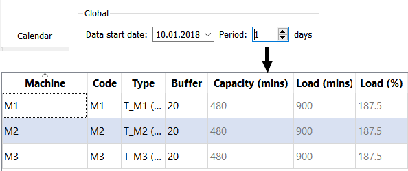
On the contrary, for a shorter period of time might endangering the ability to produce the batch and result in machine overburden (example 2:187.5%)
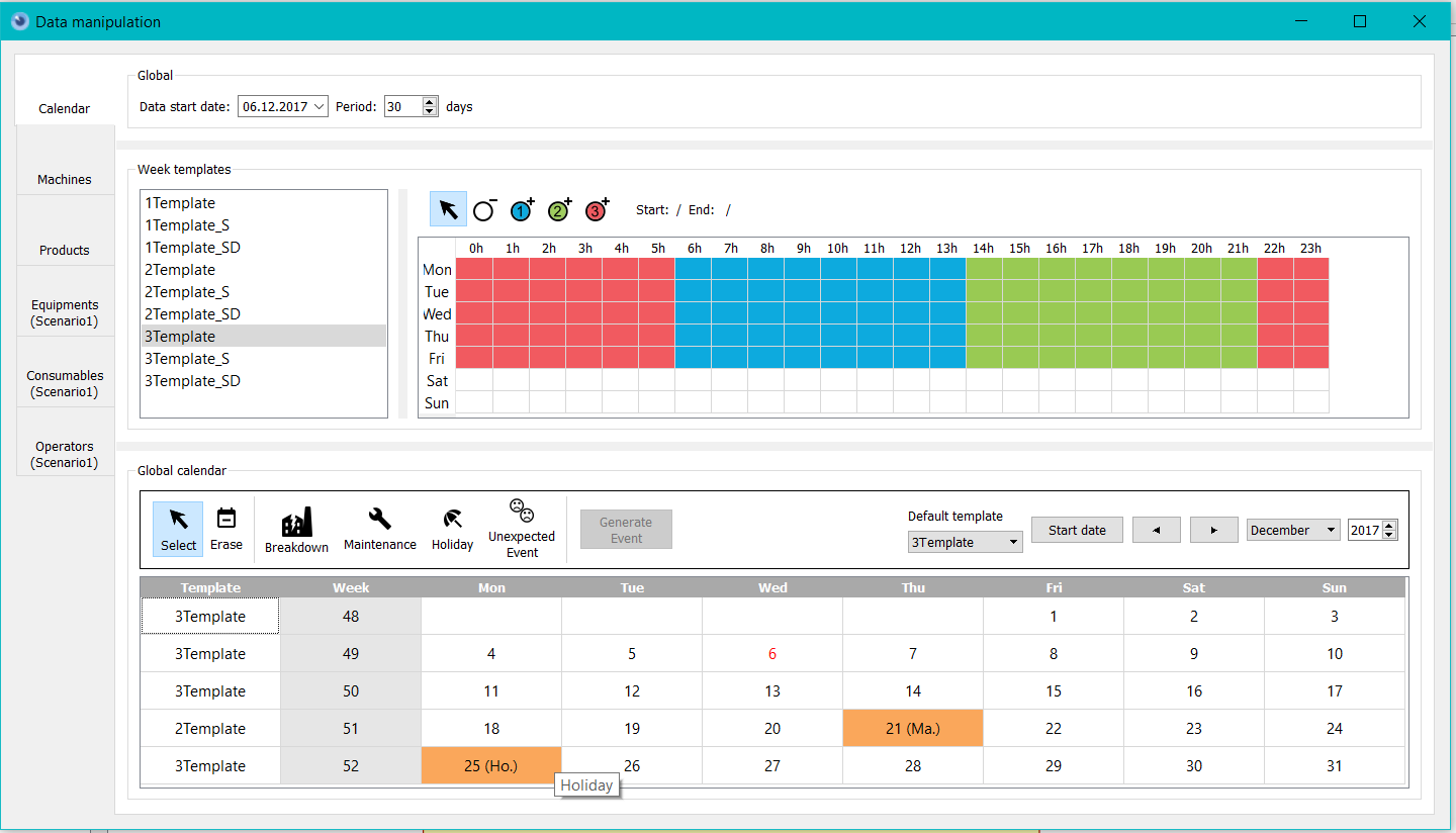
Typical Week (Shifts)
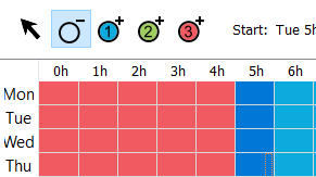
The righten part of the window defines the “typical weeks” or shifts. A typical week is a definition of the production shifts during a week. From Monday to Sunday, a shift schedule can be added/modified/deleted throughout the entire day (24h). On the left, default typical weeks are offered, they are industry standards. On the right, the schedule and shifts of the selected week is depicted with colours.
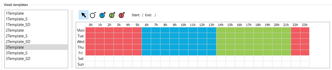
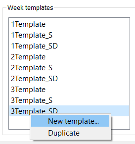
By right clicking, the user has the possibility to add new typical weeks or duplicate an existing one.
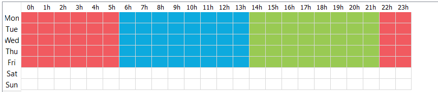
The different shifts are depicted by colors and numbers:
- the first shift in blue, has the number 1,
- the second shift in green, has the number 2,
- the third shift in r ed, has the number 3,
The maximum amount of shifts is 3 (without custom development). For a machine, a shift decomposition has no impact. The machine will be available (open) during the whold time defined through the different shifts. On the contrary, an operators will be assigned to a defined shift. In the example above, we can see that the template machine has 3 shifts from Monday to Friday.
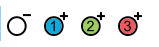
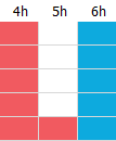
There are 4 ways to modify a typical week:
- delete the working period, all shifts included
- add working period for the first shift
- add working period for the second shift
- add working period for the third shift
In order to apply them, the user should select the action to apply and select the working period that will be modified by the action.
 =>
=> 
Calendar
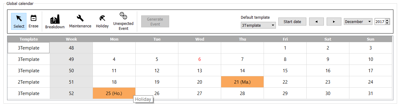
The last part of the Calendar depicts the global calendar of the factory. The calendar is arranged in the following way:
- Left-Top corner: events related actions
- Right-Top: Time related actions
- Bottom: Calendar
Typical Weeks (Shifts)
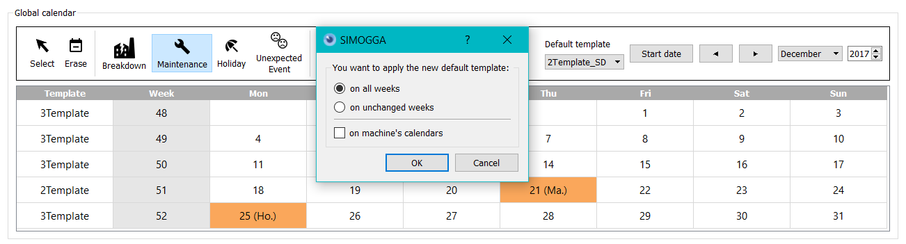
Typical shifts can be assigned by two methods:
*global, the modification is done for the whole calendar *Specifically, for a specific week
Events
We define events as exceptions that are : - time limited to specific days or period or time - hindering the production ability of the factory As of today, events have to be defined by day.
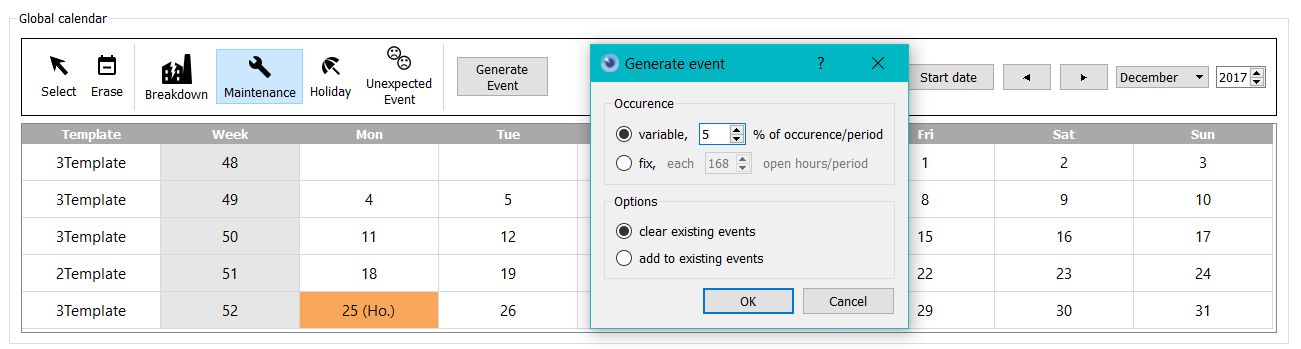
There are two ways to add en event: *Manually: Clicking on the event in the upper left and selection of the calendar cells to apply the modification *Generated: clicking on the event in the upper left and clicking on “generate event” To generate and event, there are 2 options:
- occurrence :
- Variable, it is the percentage of occurrence of such events during the period
- Fixed, the event happens at one certain moment. For instance, once every 8 days.
- The options :
- The event created in the past will be replaced by the event being defined
- The generated event add up to the formerly created events.
Machines
Machines are defined as a physical object where operations can be achieved. All the parameters related to the machines are located in the second vertical tab in the data manipulation pannel. This tab is divided in two sub-tabs: ” type and machines ” and ” calendar per machine “.
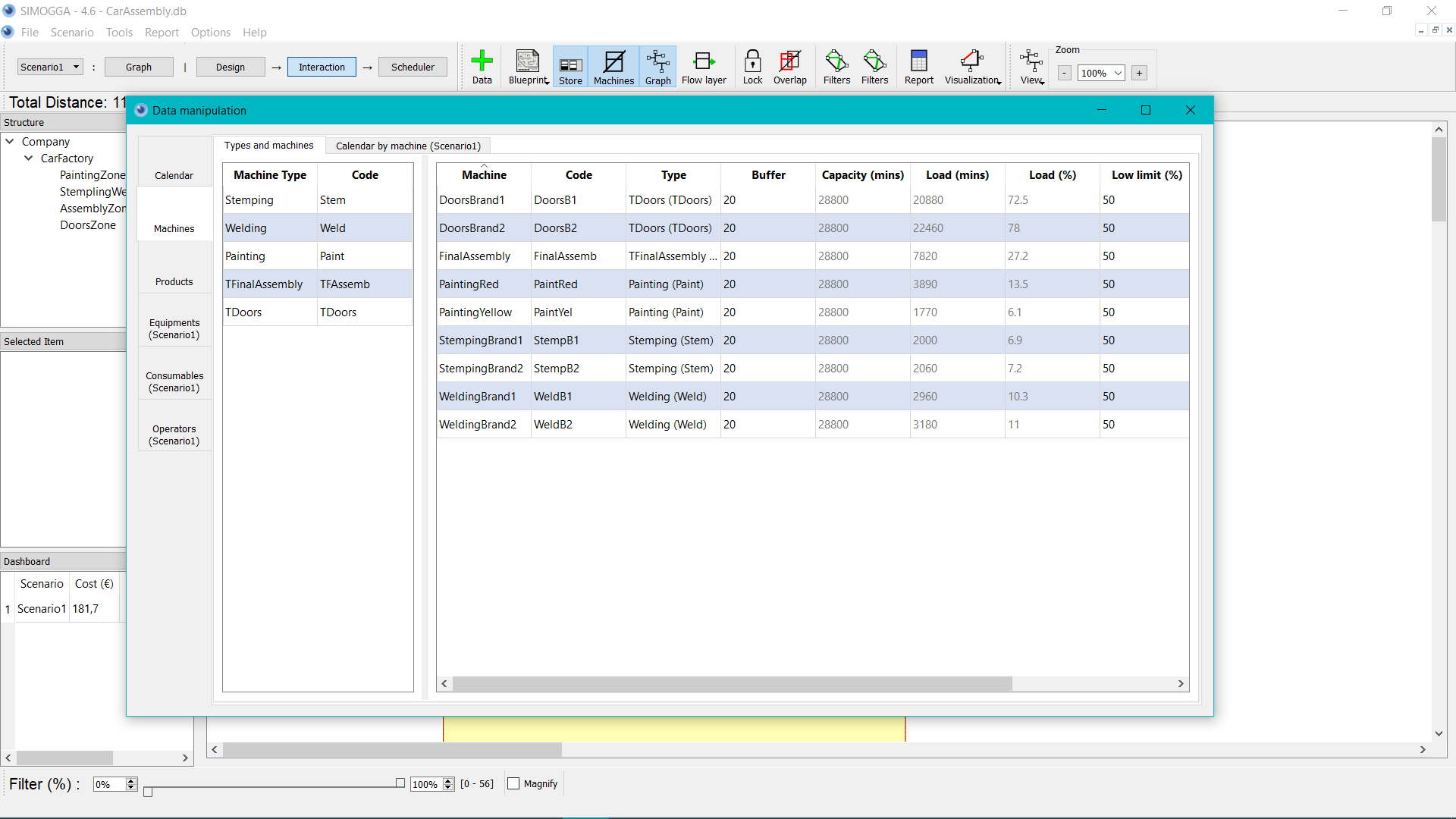
Machines and Types
In this tab, the user can create the different types of machines.
Types
The machine, allow to categorize the machines that are making similar operations. For instance: 2 painting workshops are two different physical machines. But, the painting operation can be achieved on any of the two machines. The user will then create two machines of the same type to indicate that the operation can be achieved on both.
In a nutshell: - Machines are physical location where operations are done - Machines type specific the type of operations that is being done(Category)
The tab in the left sums up the different types that can be specified for the machines.
Machine Type
The name of the type (Category)
Code
Code of type of machine, is used as an abbreviation of machine type.
Machines The machines and their characteristics are depicted in the right table.
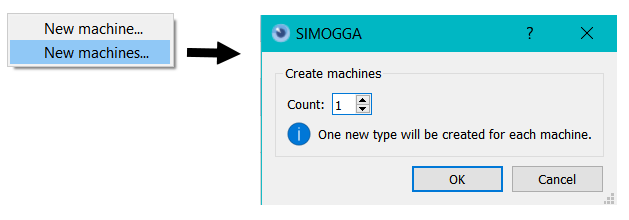
In addition to the standard add elements in SIMOGGA, you will have the choice to add multiple machines in one single operation. A new machine type will be created for each new machine.
Machine
Machine name.
Code
Machine code. Technical abbreviation of the machine name.
Type
Name and code of the machine type.
Buffer
The maximum quantity of goods in production that can be stored in front of the machine. This value is not blocking in terms of simulation but allows to make visual representation of the production when simulating.
Capacity
Maximum timing in minutes, that products can spend on the machine during a determined time period (see calendar-> global -> Period) The capacity is computed based on the working and availability schedule defined in the calendar of the machine
Load (minutes)
The load in minutes is the total time cumulated of spend by products on machines.
Load (%)
The load, in percent, is the ratio between the capacity time and the load time. A big ratio depicts a machine that is highly used. On the contrary, if the ratio is little, it depicts a low usage level.
Hint
It is possible to sort the load (%) in ascending and not ascending order to check the loads. It is recommended to always let some free capacity to manage variations.
Hint
This load is theoretical and high-level. It doesn’t take into consideration a full scale simulation. It is therefore even more important to ensure an optimal load ratio. achines surchargées (> 100%). La période devrait être réduite, s’il n’y a pas de machines surchargées et s’il y a des produits sous-chargés (<100%-marge%). La vraie indication des charges sera effectuée lors de la planification et sera visible lors de la visualisation des résultats de celle-ci.
Calendar per machine
The calendar per machine tab allows to manage the specification of the timing for each machine. The tab is divided in 3 different sections : “list of machines”, “calendar of the machine”, “global overview”.
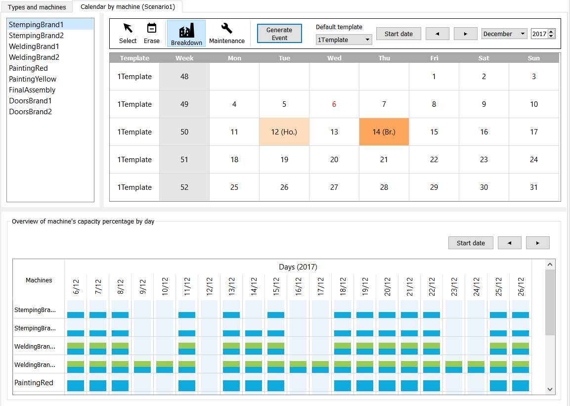
List of machines
At the top, left, are listed all the machines of the scenario that is being modified. To visualize the calendar of one machine, the user has to select it by left-clicking. The first machine is selected by default.
Machine Calendar
At the top, right, is displayed the specific calendar of the selected machine. This calendar sums up the information about the machine. The global calendar (including vents in light orange) as well as the information specific to the machine (including event in dark orange)
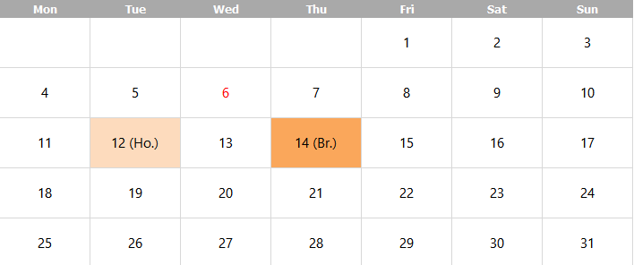
Any change on this calendar will only impact the selected machine. This calendar functions as the global calendar, with events related to specific machines: maintenance and breakdown.
Global overview
At the bottom, a recapitulating table is displayed with a global overview of the all the machines, their shifts, their breaks on a period of time. How to understand this overview? Let’s discover it with an example?
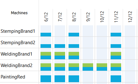
Observations on the machine StempingBrand1 :
- Only the blue color is present : the machine is only open during the first shift.
- 7/12 (Thursday) no color : seeing that the other machine are available the 07/12, something specific must happen to the machine.
If we look into the specific calendar, we will indeed see that there is breakdown on this day. *12/12 no color: no other machine is open the same day, there must be a global off day for the whole factory. This hypothesis is verified by verifying the global calendar or a machine calendar. By looking the calendar of “StempingBrand1”, an off-day is visible:
Observations on machine WeldingBrand1 :
- Blue and green colors are depicted: the first and second shift are used.
- In comparison with WeldingBrand2, the 9th and 10th of December are off-days. Both have similar typical weeks. Nevertheless, WeldingBrand2 is also working during the weekends.
Observations on machine PaintingRed :
- The typical week is similar to the one of StempingBrand1. Indeed, the model has been duplicated and the length of the first shift extended.
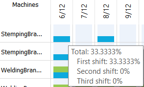
The typical week of StempingBrand1:
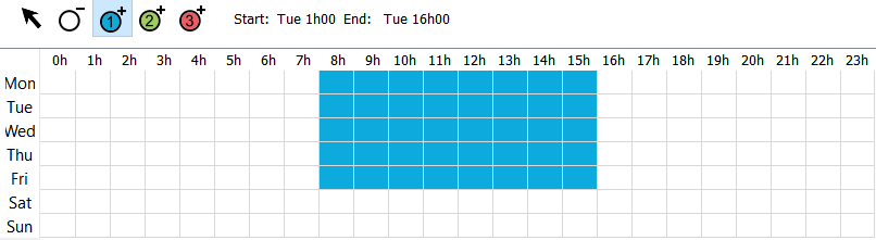
By hovering a machine/day cell with the mouse, the availability percentage based on a day (24h) will be displayed. For instance: by opening one shift out of three, from 8h to 16h, the availability will reach 33%.
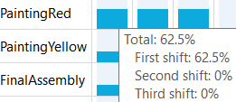
Typical week of PaintingRed :
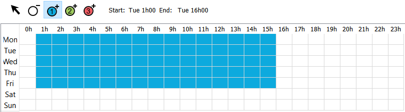 The availability percentage reaches 62.5% with opening hours ranging from 1h to 16h.
Products
A product is the result of a succession of operations (transformation and assembly of raw material and semi-finished products). The production process is the sum of all the production steps. Each operation is achieved by a certain, defined type of machine.
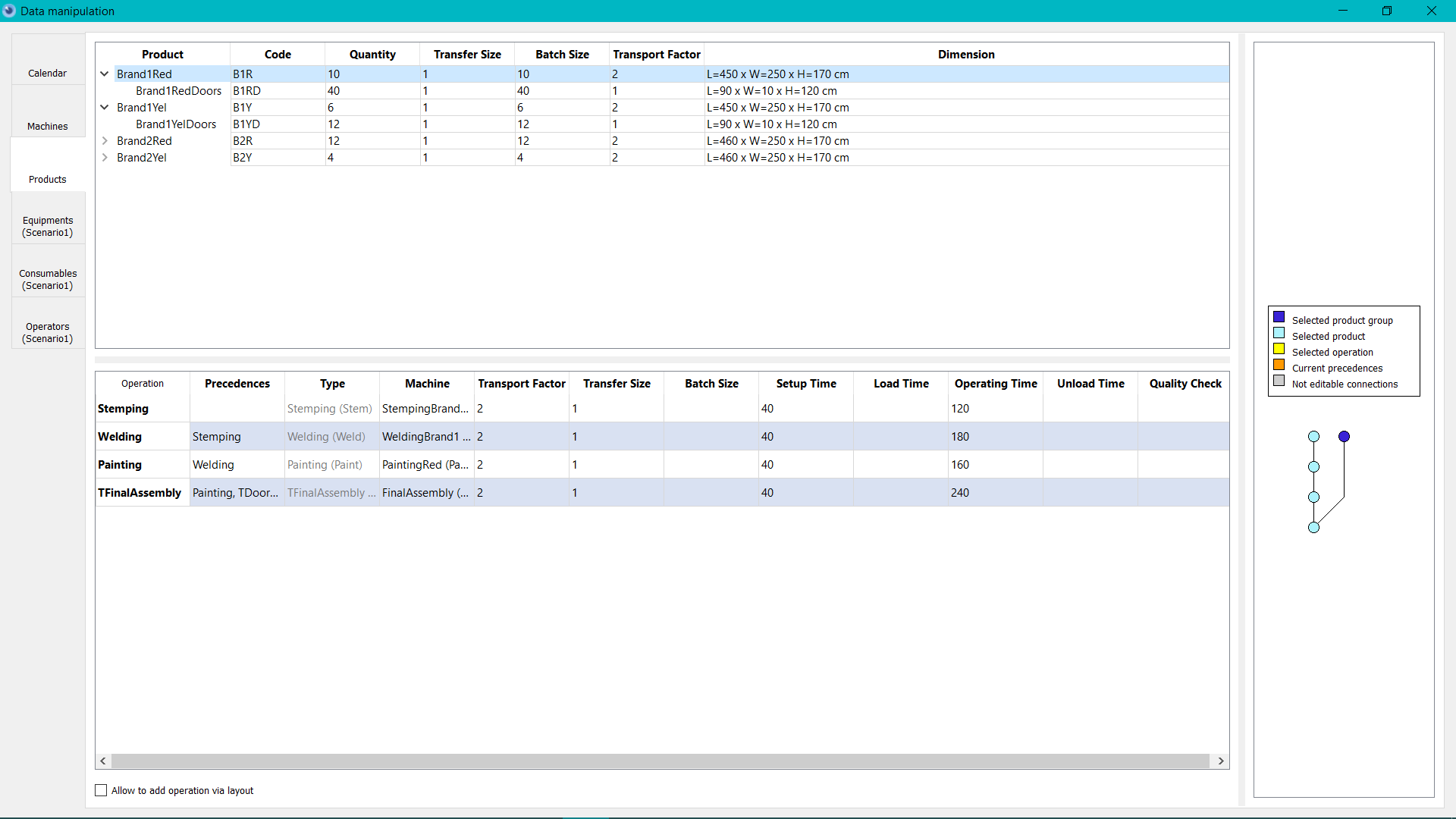
Products
At the left top corner are displayed the Products.
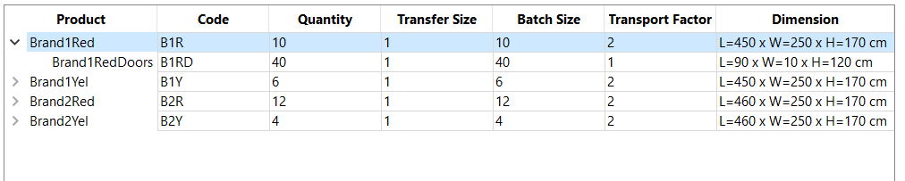
Sub-Products
A product is a succession of raw material transformation but may also contain assembly steps with other semi-finished products. The link between a product and its parent is visible when the product menu is pulled down (displayed)
Products Group
A product and its sub-products form a product group.
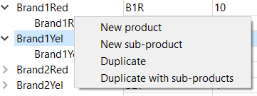
Actions** The user has the possibility to add a simple product or a sub-product. A product can be duplicated with or without its sub-products. The process and the operations will be duplicated.
Product
Product name
Code
Product code
*Quantity *
Quantity
Transfer size
The maximum amount of products that can be transferred between two machines. The transfer size must be a multiple of the lot size.
Lot size
The maximum amount of units that can be simultaneously produced. The quantity must be a multiple of the lot size.
Transport Factor
The transport factor is the multiple applied to the transport time/load between two machines. It allows to ponder transfer time to take into consideration difficult transfer. A slower product will have a higher transfer factor. It will also be displayed with a thicker flow in th visualization mode.
Dimension
The length, wight and height of a production. It will be taken into consideration for the visualization of the buffers.
Operations
At the bottom left, the principal process of the selected product is displayed. By default, the first product is selected. The product process is the sum of the operations on the product. An operation is a specific transformation of raw material of the assembly of other products and semi-finished products.
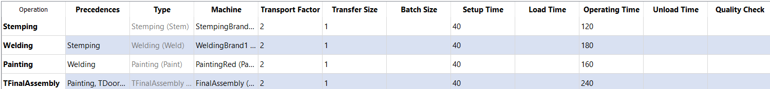
Operation
Name of the operation
Precedences
List of the operations that have to be achieved before launching this operation. All of these have to be done before launching the selected operation.
Type
Machine Type that is able to execute the operation.
Machine
The machine that will run the operation amongst the different machines of this type. The displayed configuration (size, time, etc.) are dependent from the selected machine. Example: The assembly type that has two possible machines: an old one and a new one. The operation might be achieved on the new one with a certain time but we might choose to use the old one and re-assign the operation on another machine.
Transport Factor
The transport factor is a multiple applying to the transfer from one machine the one where the next operation will be achieved. If no factor is defined at the operation level, then the factor level of the transport will be taken into consideration. The factor will mostly impact the visualization of the flows. Indeed, the factor will multiply the size of the flow rendered. So that the user know that these movement have to be minimized.
Transfer size
Ht maximum amount of units that can be transferred from one machine to the next in one single movement.
Lot size The amount of units that can be produced at the same time during the operation. If no lot size is defined with the operation, the product lot size will be taken into consideration. The default lot size must be a divider of the quantity.
Setup Time
The setup time (minutes) is the amount of time needed to set the machine up. This time will be used to take the setup time into consideration when a machine will start producing a different kind of product.
Loading time
The time to load the units on the machine (minutes)
Operating time
Time (in minutes) to run the operation.
Unloading time
The time (in minutes) to unload the product units from the machine.
Quality check time
The time needed for quality check time.
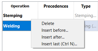
Actions
The adding of a new operation is done at the end of the process by default. While adding a new operation that requires that selection of a machine type.
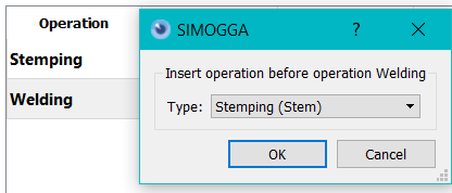
It is also possible to insert an operation after or before an existing one.
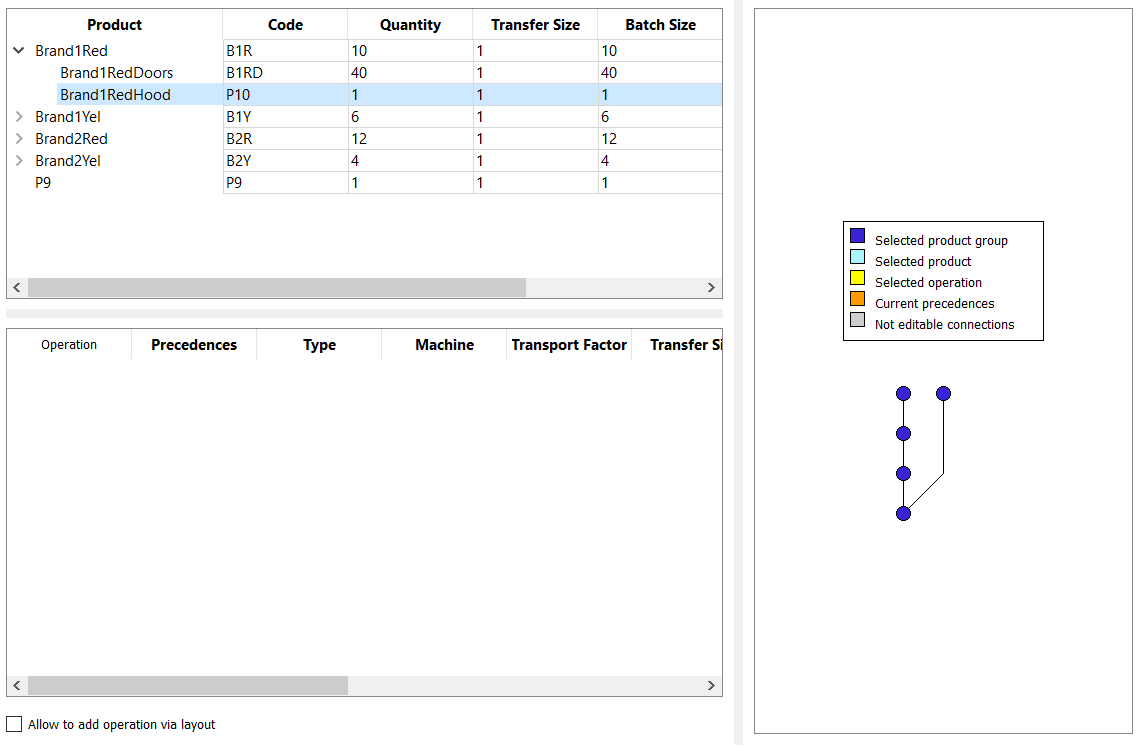
Precedences
At the right of the tab, the process flowchart with precedences is displayed. As a reminder, the precedence B of operation A is an operation that must be achieved on a semi-finished product before that operation A may start.
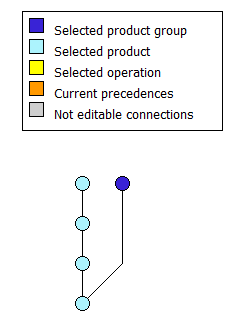 An operation is depicted as a node on the graph. By hovering the node with the mouse, the user receives the informations about the operation.Une opération est représentée par un nœud sur le graphe, en passant le curseur de souris au-dessus d’un nœud, on obtient les informations sur l’opération.
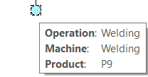
Color code :
- Light blue : operations of the selected product
- Dark blue : operations of the product group
- Yellow : Selected operation
- Orange : Precedences of the selected operation
- Grey : Operations that can’t be edited (operation that must stay at the beginning or the end of the process)
Link between the left and right panel
The same data are depicted in a different way. If you select one operation it will be selected in both panels.
edit precedences
There are two ways to edit :
- Table : double click on the cell in the precedences column
- Graph : Right click on the node and then on the menu “edit precedences”
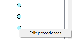
The editing is done by clicking on the nodes in the graph.
- If the clicked node was a precedence, it will be unlinked.
- If the clicked node was not a precedence, it will be added.
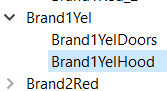
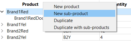
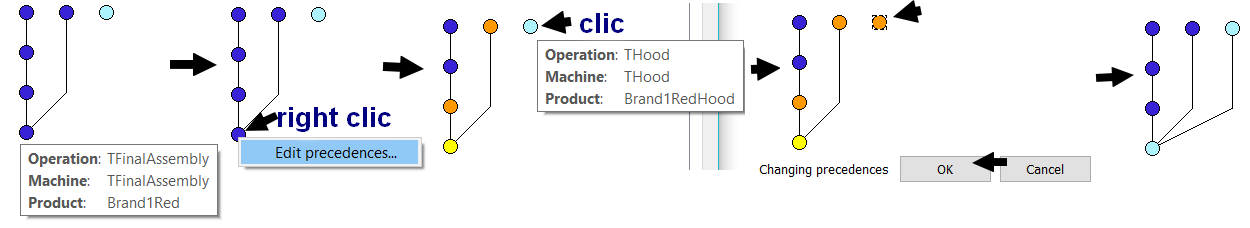
Example : How to add a sub-product to a product?
Exercise : add a new sub-product to « Brand1RedHood » to the product « Brand1Red ».
Steps :
1. Right click on « Brand1Red » and « Create sub-product ».
2. Double-click on the new sub-product and change the name in « Brand1RedHood », press enter to validate.
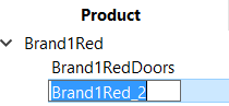
3. The sub-product is included in the product group “BrandRed1” with no operations at the moment.
- Right click on the operations table and selection “insert last” in the menu.
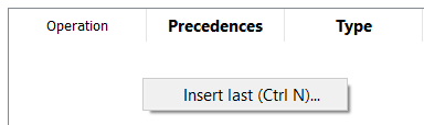
5. Choose the operation type to add.
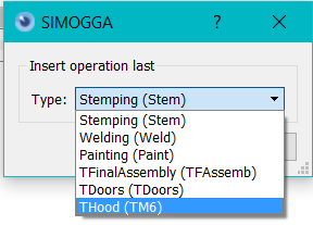
6. The new operation is now created.
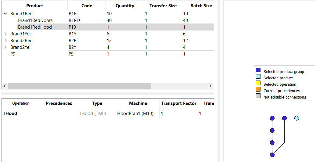
- Link the sub-product to the parent product.
7.1 Right-Click on the assembly operation of the parent product.
7.2 Click on “edit precedence”
7.3 Click on the operation to bind
7.4 Validate
The sub-product has been entirely created. You can now see that in the “Brand1RedHood” operations table that the assembly operation is visible. As this operation belongs to the parent product, it is not editable.
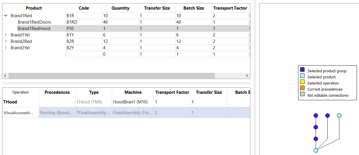
The two sub-products have correctly been connected to the principal product. It can be verified by looking at the precedence tree.
Equipments
An equipment is a tool, machine or equipment that allow to move the product between machines or during a part of the whole production process. On an automated production line, a clamp will move a product from machine A to machine B. An equipment that is active throughout multiple operations can be a conveyor or an crane that will carry a car in assembly.
Equipments Type
An equipment type is a group of similar equipment. When inputting parameters to the planner, an operation might be linked to a certain type of equipment.
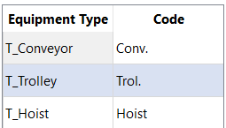
Equipments Type
Name of equipment type.
Code
Equipment type code
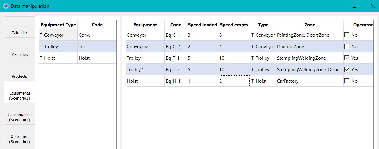
Equipments
An equipment is a tool, machine or equipment that allow to move the product between machines or during a part of the whole production process.
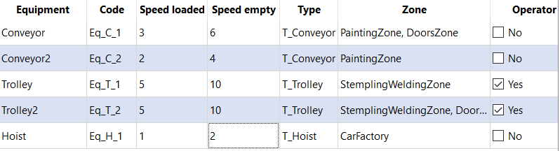
Equipment
Equipment name
Code
Equipment code
Speed loaded
Speed in km/h when the equipment is moving and loaded (carrying product)
Speed empty
Speed in km/h when the equipment is moving and empty (not carrying product)
Type
Equipment Type
Zone
The zone where the equipment is active. Equipment can be restricted to certain zone. Zone are defined with parents (Site > Building > Floor > Room > Cell). The equipment can be assigned to a zone at different levels and will be active in all the lower level subzones.
Operator
The equipment will or won’t need the presence of an operator. A cart will need an operator. An automated crane won’t.
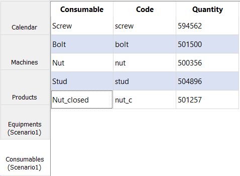
Consumables
A consumable is a kind of good that will entirely disappear in the production process (for instance: a screw, a bolt, etc.) The assignment of a consumable will be done while parameterizing the planner.
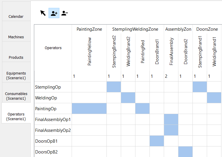
Operators
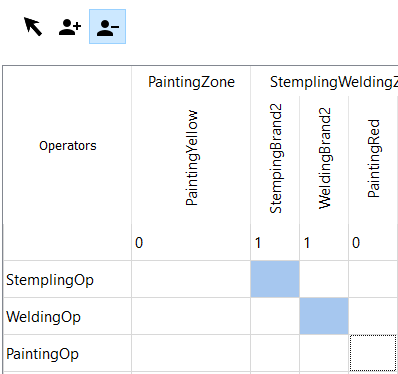
An operators is a factory worker that belongs certain competencies allowing him to work on certain machines. His skills will also define which kind of equipment he will be able to manipulate (see planner configuration). The machines skills are sorted by zone. It allows to easily find the skills to assign to an operator based on the layout. Each machine skill sums up the amount of operations that are assigned to it.
Actions
Delete
- Select Delete action
- Select the zone to delete
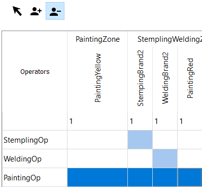
- Release the mouse button to apply delete action. The operators counters and the visual are updated
Assignation
- Select assignation action
- Select cells where to apply the action
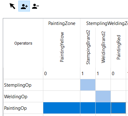
- Release mouse button to apply assignation. Operators counters and visuals are updated.
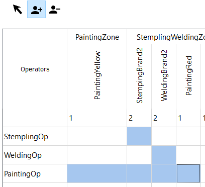
Selection
Allow to select cells without applying changes. It allows to prevent modifying cells without purpose.